Session 3 — Comparing SDK GPIO and Register-Level Timing
Goal (one sentence): Compare the output signal and execution speed between the SDK's gpio_put calls and direct register-level GPIO writes on the Pico 2 W.
Prediction — written before running anything: The SDK's gpio_put should run slower than writing straight to the SIO registers, since each call goes through extra function-call and pin-validation overhead before it touches the pin; on the scope that should show up as a noticeably lower toggle frequency for the SDK version than for the register-level version.
Setup
- Pin map:
LED= GP18, driving the LED output; oscilloscope CH probe connected to GP18.
What I did
- Wired the Pico 2 W to a breadboard and started a new "Blink" project from the VS Code Pico extension.
- Flashed and ran the SDK version (
gpio_put) first. - Connected and calibrated the oscilloscope to read the toggle frequency.
- Replaced the SDK calls with direct writes to
sio_hw->gpio_set/sio_hw->gpio_clr. - Measured again with the oscilloscope, same settings.
Evidence
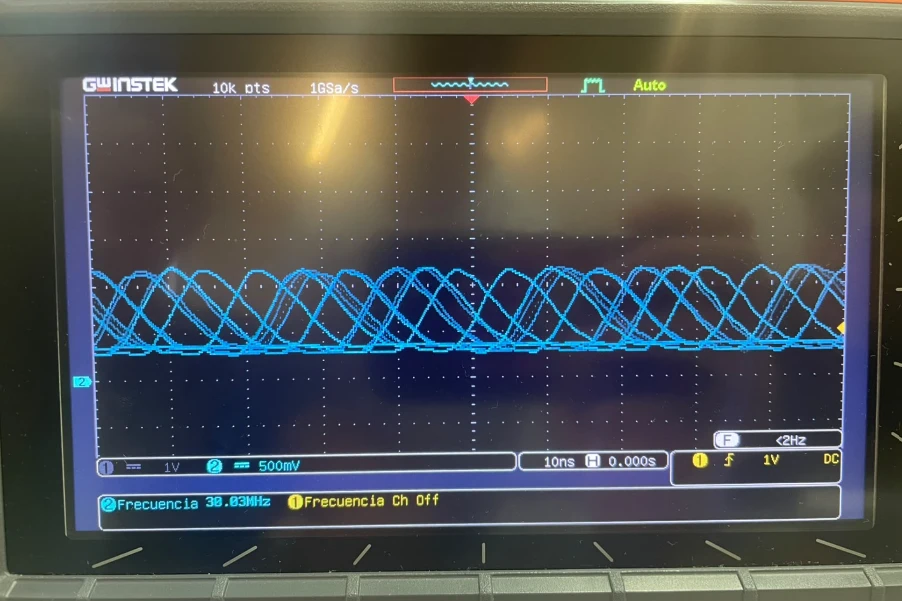
This is the signal we captured on the register-level version: 38.03 MHz, toggling with no delay between writes — dramatically faster than the SDK version, which matches the prediction that removing gpio_put's call overhead lets the pin toggle much faster.
What went wrong
- Our Pico 2 W burned out partway through the exercise for an unknown reason, and we were left without a board. We ended up finishing the exercise working together with classmates on their hardware.
Code
SDK
Register-level
const uint32_t LED_MASK = 1u << LED;

gpio_init(LED);
sio_hw->gpio_oe_set = LED_MASK;

while (true) {
    sio_hw->gpio_set = LED_MASK;
    sio_hw->gpio_clr = LED_MASK;
}
Open Question
The register-level loop reached tens of MHz with no added delay at all — is that ceiling set by the GPIO pad's own drive strength and rise time, by the SIO bus clock, or just by the two-instruction loop overhead itself? I'd like to pad the loop with asm volatile("nop") instructions to see which one is actually the limit.